Trapezoidal (Six-Step) Commutation
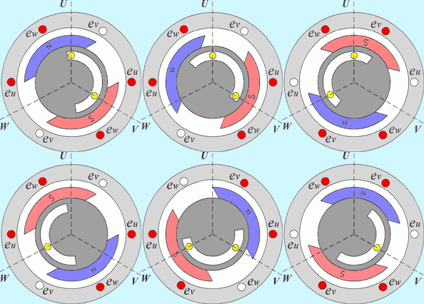
The simplest electronic scheme divides one electrical revolution into six steps, each 60° apart. In each step, exactly one phase is driven high, one is driven low, and one is left floating (disconnected), the floating phase is actually useful, because its back-EMF voltage tells the controller when the rotor has advanced far enough to move to the next step. Six inexpensive Hall-effect sensors (or a lookup based on back-EMF zero-crossings) are all that's needed to know which of the six steps to use next.

Source: Wikimedia Commons
Source: Wikimedia Commons
Think of it like a brushed commutator with six segments instead of two, the effective "push" direction hops around the motor in six discrete jumps per electrical revolution instead of one smooth mechanical sweep. That's cheap and simple to implement, and it was the standard approach for early affordable brushless ESCs, but it has a real cost: because the driving force jumps in sudden 60° steps rather than gliding smoothly, the torque output ripples up and down within every step, producing audible whine, extra vibration, and reduced efficiency, especially at low speed.
The natural fix, is to stop jumping and glide instead. see sinusoidal commutation.