Torque, Current, Speed, and Voltage
Every motor, no matter which commutation scheme drives it, obeys two more relationships once it's actually spinning: torque tracks current, and speed tracks voltage, kind of. Both come straight from the same Lorentz force that started this whole section.
Torque Is Proportional to Current
The Lorentz force law says a current-carrying wire in a magnetic field feels a force, and torque is just that force acting at a radius. Everything about a specific motor that affects the size of that force, field strength, number of turns, radius, is fixed, so it can all be bundled into one constant, the torque constant :
More current, more torque, in direct proportion. This is the same from Field-Oriented Control's , and it's why a current limit in code is really a torque limit in disguise, capping current caps how hard the motor can push.
Speed Is Proportional to Voltage, Kind Of
Here's the catch: a spinning coil is also a generator. The same current-to-field relationship from Electricity and Magnetism Are Linked runs in reverse too, a wire moving through a magnetic field has a voltage induced in it, called back-EMF, that always opposes the applied voltage and grows with speed (). The full circuit looks like this:
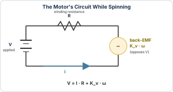
At no load, almost no current flows, so speed really is close to proportional to voltage: . Under load, some voltage gets spent pushing current through resistance instead, so real speed always sits a bit below that. Voltage sets a ceiling on speed; how close the motor gets to it depends on load.
Reading a Motor Curve
Every FRC motor datasheet publishes a motor curve: torque, current, power, and efficiency all plotted against speed, at a fixed voltage. It's the same relationship from above, just drawn out instead of solved algebraically, and learning to read one tells you everything about how a motor behaves anywhere between rest and full speed. Here's the Kraken X60, running Trapezoidal and then FOC commutation:
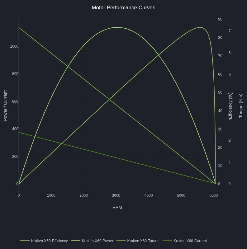
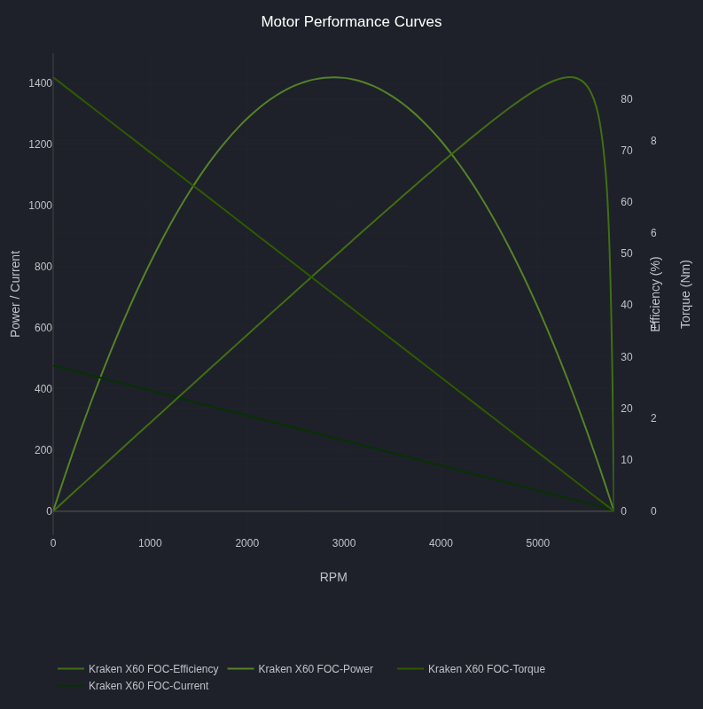
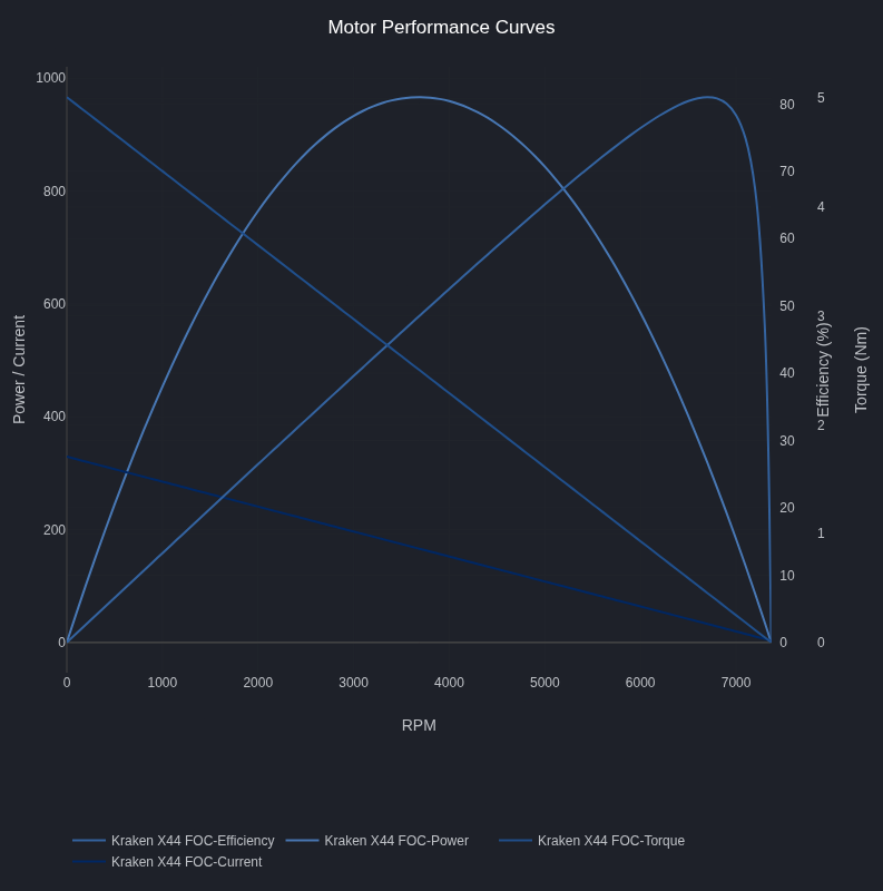
Every curve on the chart runs left to right, from stall (speed = 0) to free speed (torque = 0):
- At stall, the motor isn't turning, so there's no back-EMF at all to oppose the applied voltage. That means the winding resistance alone limits current, so torque and current are both at their maximum, and power is zero (nothing is moving yet, so no mechanical work is being done).
- At free speed, the motor has sped up until back-EMF cancels out nearly all of the applied voltage. Only a trickle of current gets through, the free current, just enough to overcome friction, so torque and power both drop back to zero.
- Power () is zero at both ends and peaks in the middle, since it needs both torque and speed to be nonzero at once. Efficiency peaks even further toward the free-speed end, since a small torque loss to winding heat matters less relative to output as speed climbs.
Pick any speed on the x-axis and read straight up: each curve tells you what that quantity is doing at that operating point. A mechanism that needs a lot of torque, driving into a stall or accelerating a heavy load, operates on the left side of the chart and draws current close to the stall value; that's exactly why current limits matter so much, they cap how far left the motor is allowed to run. Notice the FOC chart's higher stall torque and current than the trapezoidal chart, that's the practical payoff of the smoother, more precisely regulated current from Field-Oriented Control: the controller can push closer to the motor's real thermal limit with less margin lost to ripple.
The smaller Kraken X44 shows the exact same shape, just scaled down, proof that this is a general pattern and not just a coincidence of one motor's construction:
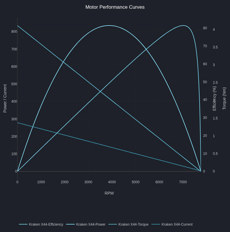
Both relationships hold regardless of how the current actually gets switched around inside the motor, brushed or brushless. Continue to Torque Ripple Across Commutation Methods to see how those four commutation schemes actually compare.