Brushless Motors (BLDC)
A brushless motor solves the wear problem brushed motors run into by rebuilding it inside out.
Part One: Windings on the Stator
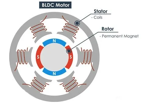
Instead of a fixed magnet, the outer, stationary stator now holds the winding, the coil of wire current flows through. A brushless motor usually splits its winding into several independent groups called phases (most commonly three, labeled A/B/C or U/V/W), spaced evenly around the inside of the housing. Each phase can be energized on its own, which is what will let the motor "aim" its magnetic push in different directions later on.

Source: Wikimedia Commons
Part Two: Magnets on the Rotor
The rotor, the part that's free to spin on the shaft, now carries the permanent magnets instead of the winding. Since a permanent magnet doesn't need current to make a field, nothing on the rotor needs an electrical connection at all, which is the whole point: with no current-carrying part ever touching anything, there's nothing left to wear out.
Part Three: A Position Sensor
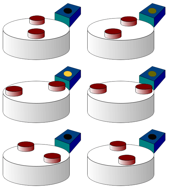
Swapping the magnet and the winding creates a new problem: in a brushed motor, the commutator physically knew when to flip the current, because it was mounted right on the spinning shaft. Here, nothing is physically connected to the spinning magnets anymore, so the motor controller has no way to feel where the rotor is on its own, it has to be told. The simplest way to tell it is a Hall-effect sensor: a small fixed chip that outputs a signal whenever a magnet passes close by. Mount a few of these on the stator, and the controller gets a signal each time one of the rotor's magnets sweeps past, enough to know, roughly, which way the rotor is currently facing.
Source: Wikimedia Commons
Putting Them Together
Now the pieces combine differently than before: if nothing physically switches the current anymore, what does the job the commutator used to do? The magnets are on the part that's free to spin, so the only way to keep pulling them around is to electronically energize the surrounding stator phases in the right sequence, always a little bit "ahead" of wherever the position sensor says the rotor's magnets currently are, so the rotor keeps chasing a target that keeps stepping out of the way.
This means a brushless motor controller, an ESC, or in FRC's case something like a TalonFX or SPARK controller, has to know where the rotor currently is before it can decide which phase to energize next. Cheap Hall-effect sensors like the one above are enough for a coarse read; a magnetic or optical encoder gives a much finer, continuous read of the exact angle instead of just "a magnet went by."
This is why a brushless motor "hunts" or won't spin cleanly if its position sensor is disconnected or miscalibrated, the controller has genuinely lost track of where the magnet is, and a badly-timed commutation pushes the rotor backward instead of forward, the same failure mode as a brushed motor with no commutator at all.
There are two common ways to decide the electronic switching sequence: trapezoidal (six-step) commutation, and sinusoidal commutation. Both are still just commutation, flipping which phases are energized to keep chasing the rotor, they differ only in how smoothly they do it.