Brushed DC Motors
Now let's actually build a motor, one part at a time, using nothing but the Lorentz force from the previous page.
Part One: A Fixed Magnetic Field (the Stator)
Every motor needs a steady magnetic field to push against, and the simplest way to make one is with a permanent magnet, the same kind of magnet that sticks to a fridge. Every magnet has two ends, called poles: a north pole and a south pole. Between the poles, an (invisible) magnetic field points from north to south, and that field is exactly what the Lorentz force needs to have something to push against.
In a simple motor, this magnet is curved into a ring and fixed to the inside of the motor's outer housing, so it never moves. This fixed, outer part, magnet and housing together, is called the stator, short for "stationary."
Part Two: A Wire Free to Spin (the Rotor)
Next, the motor needs a wire that current can flow through, sitting inside the stator's magnetic field and free to move. Instead of one straight piece of wire, real motors wrap the wire into a loop (or many loops), called a winding, coiled around a cylinder of iron called the core that helps concentrate the magnetic field. The core and its windings are mounted to a central metal rod, the shaft, which rests on bearings so it can spin freely. The core, its windings, and the shaft together are called the rotor (or the armature), this is the part of the motor that actually turns.
Putting Them Together
Slide the rotor inside the stator so the winding sits in the magnet's field, then run current through the winding. Current flows one way down one side of the loop and back the other way down the opposite side, same wire, opposite directions. By the Lorentz force, each side of the loop feels a sideways force, and because the two sides carry current in opposite directions, those two forces don't cancel each other out. Instead, they combine into a torque: a twisting force that spins the rotor around its shaft.

Source: Wikimedia Commons
That's a complete, working, if extremely simple, motor: a stator to supply a fixed magnetic field, a rotor free to spin inside it, and current flowing through the rotor's winding to produce torque. There's just one problem with it, which is the entire subject of the rest of this page.
Why a Loop Alone Isn't a Motor
Here's the problem: as the loop spins past the halfway point, the side of the loop that was under the north pole is now under the south pole, and vice versa. If the current through the loop never changed direction, the force on that side would now point the wrong way, it would try to push the loop backward instead of forward. A simple loop of wire connected to a battery doesn't spin continuously; it wobbles into alignment with the field and stops, like a compass needle settling.
To keep spinning, the motor needs to flip the current in the loop every time it crosses that halfway point, so that the side of the loop under the north pole is always carrying current in the same absolute direction, no matter which physical half of the loop happens to be there at the moment. This is the entire job of the commutator: a metal ring, mounted on the shaft and split into two separated halves (one end of the loop soldered to each half), that spins along with the rotor. Power reaches the commutator through a pair of brushes, small, spring-loaded blocks of graphite or copper, fixed to the stator, that press against the spinning commutator to complete the circuit. As the rotor turns, the brushes themselves never move, but which half of the split ring each brush is touching swaps every half-turn, and that swap is what reverses the current in the loop at exactly the right moment.
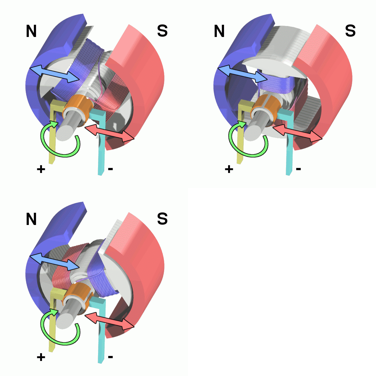
Source: Wikimedia Commons
This mechanical trick, physically swapping which wire is connected to positive every half-turn, is commutation. Every other technique covered in this section, all the way up to FOC, is really just a different way of solving this exact same problem: keep the torque pointed the same way while the thing producing it spins underneath you.
This is the single most important idea in this whole section. A magnet chasing a magnetic field only produces useful, continuous torque if the field keeps moving out of its way at the right moment. Brushed motors do this mechanically with a spinning switch. Every "electronic commutation" scheme covered on the following pages is doing the exact same job electronically instead.
Real brushed motors (like the CIM and 775pro) use many coils and many commutator segments instead of just one loop and one split ring, this smooths out the torque ripple you'd otherwise feel as each coil gets switched, but the underlying mechanism is identical to the two-segment version above.
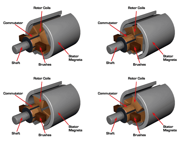
Source: Assun
Controlling Speed: PWM and the H-Bridge
A brushed DC motor's speed is (roughly) proportional to the average voltage applied across it, and its direction is set by which way that voltage is applied. Robot electronics don't have a dial that outputs "6.3 volts", motor controllers only really have switches. So instead of varying the voltage directly, they switch the full battery voltage on and off very quickly (tens of thousands of times per second) and vary the fraction of time it's on, its duty cycle (covered in more depth in the Hardware Communication addendum), just used here to shape raw power instead of to send a command. This is Pulse Width Modulation (PWM). A motor's winding acts like a low-pass filter, electrically, it "feels" the average of a fast-switching square wave, not the individual pulses.
Direction is handled by an H-bridge: four switches arranged so that the motor can be connected to the battery in either polarity.

Source: Wikimedia Commons
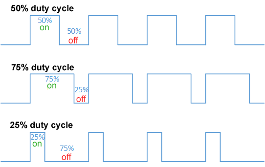
Source: Wikimedia Commons
Where is the duty cycle (0 to 1) and is the battery voltage. This is the mechanism underneath everything described in Open Loop Control, when you command a motor to "50% power," you are, at the lowest level, asking an H-bridge to hold its switches on for half of every PWM cycle.
Where Brushes Fall Short
Physical brushes dragging against a spinning commutator work, but they come with real costs:
- Mechanical wear, brushes are consumable parts that wear down and eventually need replacing.
- Sparking, every time a brush crosses the gap between commutator segments, it briefly breaks a live circuit, which arcs. This wastes energy, generates electrical noise, and is why brushed motors need lower operating voltages as speed and segment count increase.
- Heat and friction, the physical contact between brush and commutator resists motion and generates heat that has nowhere to go but the tiny contact patch.
- RPM ceiling, spin the commutator fast enough and the brushes can't maintain reliable contact.
Every one of these problems disappears if you can find a way to commutate the current without physical contact at all. That's exactly what a brushless motor does.