PWM: Pulse Width Modulation as a Command
The simplest way to use duty cycle to send a command is Pulse Width Modulation (PWM): repeat a pulse at a regular rate, and let the width of the high pulse, not just its percentage of the period, carry the meaning. Neither the repeat rate nor the range of widths is fixed by PWM itself, those are just a convention that whoever designs a particular device gets to choose, and the sender and receiver simply have to agree on ahead of time. Different devices, including different motor controllers, use different conventions.
One especially well-known example is the convention used by classic RC hobby servos, where a 1 millisecond pulse means one extreme, a 1.5 millisecond pulse means centered or stopped, and a 2 millisecond pulse means the other extreme, with everything in between mapped smoothly across that range. Plenty of PWM-based motor controllers borrow this same pulse-width idea, even when the rate they repeat that pulse at differs from device to device.
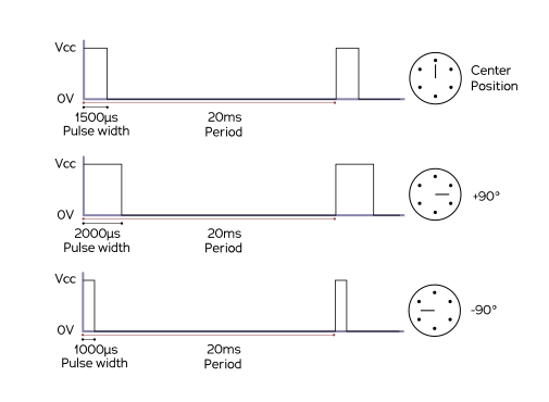
Source: Wikimedia Commons
For more details and specifics, see here
Resolution: How Finely Can a Pulse Width Represent a Value?
Whatever is generating the pulse, whether that's a microcontroller or an FPGA, isn't measuring or producing pulse width as a smooth, continuous quantity, it's counting ticks of an internal clock. If that clock ticks a million times a second, the shortest possible difference between two pulse widths it can produce is one tick, or one microsecond, so a 1-to-2-millisecond command range could only ever be divided into about a thousand distinguishable steps. Run that same clock faster, or spread the command range over a wider span of pulse widths, and PWM can represent more distinct values; the tradeoff is that a wider range, or a slower repeat rate, means the receiving device has to wait longer between updates to get the next command. This is exactly the same resolution-versus-speed tradeoff every digital timer runs into, and it's why not every device that uses PWM commands agrees on the same repeat rate or pulse-width range in the first place: each one is a different point on that same tradeoff.
Where PWM Falls Short
PWM is simple and cheap: it needs only one signal wire (plus power and ground) per device, and the receiving device doesn't need to do much beyond measuring how long each pulse stays high. That simplicity is also its ceiling, PWM only flows one direction (the roboRIO can tell a device what to do, but the device has no way to talk back), and every device needs its own dedicated wire back to the roboRIO, which doesn't scale well as a robot grows. Everything covered on the following pages exists to fix one or both of those limitations.
Don't confuse this use of PWM, a command signal sent over one wire, with the PWM discussed in Brushed DC Motors, where a motor controller uses a much faster internal PWM signal to switch an H-bridge and control the actual voltage reaching the motor. Same underlying trick (duty cycle), two completely different jobs.
Continue to UART to see the first fix: a signal that can talk back.