I2C: Inter-Integrated Circuit
I2C (Inter-Integrated Circuit) takes the opposite trade-off from SPI: instead of a dedicated select wire per device, every device, no matter how many, shares just two wires total: SDA (data) and SCL (clock). Each device is given a unique address ahead of time, and the controller starts every message by broadcasting the address of the device it wants to talk to; every other device on the bus simply ignores messages addressed to someone else.
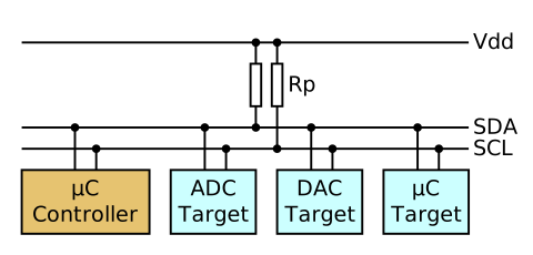
Source: Wikimedia Commons
For more details and specifics, see here
How a Bit Is Actually Sent: Open-Drain Wiring
Sharing just two wires among every device on the bus only works because of how those wires are driven. Every I2C
output is open-drain: a device can only pull a wire down toward 0 V, or release it, it can never actively drive
a wire high the way SPI or CAN outputs do. A 1 only happens because the pull-up resistors visible in the topology
diagram above passively pull a released wire back up on their own once nothing is holding it down. Because no device
ever actively drives a 1, two devices can never fight over the bus by trying to force opposite voltages at the
same time, at worst, one pulls the wire low and the others just aren't holding it high, so it reads low. That's also
exactly what lets a device that isn't currently "in control" still participate: a target device can pull SDA low to
acknowledge a byte even though the controller owns the clock, without any risk of a collision.
The I2C Message: Start, Address, Acknowledge, Stop
Every I2C message begins and ends with a specific pattern on the wires that can never appear in the middle of ordinary data: a start condition is SDA switching from high to low while SCL is held high, and a stop condition is SDA switching from low to high while SCL is held high. Everywhere else in the message, SDA is only allowed to change while SCL is low, which is exactly what makes start and stop unambiguous. Between those two bookends, the controller sends the target's address followed by a single bit saying whether it wants to write to or read from that device, and after every single byte, whichever side just received it pulls SDA low for one clock pulse as an acknowledgment (ACK), confirming the byte actually arrived before the next one is sent.

Source: Wikimedia Commons
Speed
I2C is standardized into a handful of speed grades that a device advertises support for: Standard mode (100 kbit/s), Fast mode (400 kbit/s), Fast mode plus (1 Mbit/s), and High-speed mode (3.4 Mbit/s). Even at the fastest of those grades, I2C tops out well below what SPI or CAN can sustain, which is the direct cost of getting away with only two shared wires.
Two wires for an unlimited number of devices is a great trade on paper, but it comes at a real cost: I2C is slower than SPI, and because every device shares the same two wires, a single misbehaving device can jam the entire bus.
This isn't just theoretical, the roboRIO's I2C port has a well-known history of locking up entirely (sometimes requiring a full reboot to recover) when a device on the bus misbehaves. Most FRC teams either avoid daisy-chaining many I2C devices together, or avoid the onboard I2C port altogether in favor of CAN-based sensors when one is available.
CAN bus breaks the pattern all four protocols so far have shared, entirely.