📐 Geometry Concepts
APIs and control systems change season to season, and sometimes mid-season. Specific class names, file paths, and code examples throughout this section reflect FRC 190's codebase at the time of writing and may become outdated or obsolete as WPILib, CTRE, and other vendor libraries evolve. Treat this section as a guide to the underlying concepts, not a guaranteed match to the current source.
Coordinate Frames covers which frame a number belongs to. This page covers the actual classes those numbers live in: the small set of WPILib types every piece of 190's code, drivetrain, vision, autonomous, uses to represent a position, an angle, or a motion, and what operations are actually defined on them.
Geometry Standardization
Every one of these types lives in edu.wpi.first.math.geometry, and they're immutable value objects, not raw
doubles. That standardization matters for a reason beyond convenience: it makes entire categories of bugs
impossible to write by accident. A raw double can't tell you whether it's degrees or radians, or whether it's
an absolute field position or a relative offset from something else. A Rotation2d or a Transform2d can,
because the type itself carries that meaning, and the API only offers operations that make sense for that meaning.
Terminology
Translation
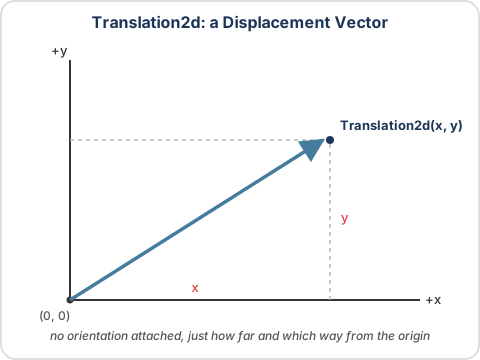
A Translation2d is a plain displacement: an (x, y) pair, in meters, with no orientation attached at all.
It supports the operations a vector should: .plus(...) and .minus(...) to add or subtract two
translations, and .rotateBy(Rotation2d) to rotate one around the origin.
Rotation
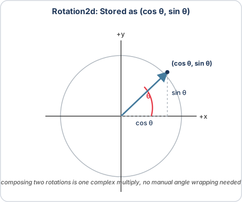
A Rotation2d represents an orientation. Internally it's stored as a (cos, sin) pair rather than a raw
angle, specifically so that composing two rotations together is a single multiplication rather than something that
has to manually wrap around at 360 degrees. .plus(Rotation2d) (an alias for .rotateBy(...)) composes two
rotations, and constants like Rotation2d.kPi (180 degrees) make common rotations easy to reach for without
constructing one from scratch.
Pose (Translation + Rotation)
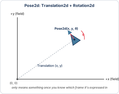
A Pose2d bundles a Translation2d and a Rotation2d together into one absolute position and heading.
"Absolute" is doing real work in that sentence: a Pose2d only means anything once you also know which
coordinate frame it's expressed in, "the robot is here, facing this
way, in the field frame."
Transform (Translation + Rotation)
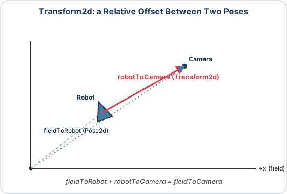
A Transform2d bundles the exact same two pieces of data, a Translation2d plus a Rotation2d, but
means something different: a relative offset between two poses, not an absolute location on its own. WPILib's API
enforces that distinction directly. There is no Pose2d.plus(Pose2d), adding two absolute positions together is
meaningless, but there is a Pose2d.plus(Transform2d), which returns another Pose2d, and a
Pose2d.minus(Pose2d), which returns the Transform2d between them.
GeometryUtil, 190's small geometry helper library inspired by FRC 6328, is built almost entirely around constructing transforms this
way:
Show code
public static Transform2d toTransform2d(Translation2d translation) {
  return new Transform2d(translation, new Rotation2d());
}

public static Transform2d toTransform2d(Rotation2d rotation) {
  return new Transform2d(new Translation2d(), rotation);
}

public static Transform2d toTransform2d(Pose2d pose) {
  return new Transform2d(pose.getTranslation(), pose.getRotation());
}
Twist
A Twist2d represents a change in distance along an arc, not a straight-line displacement. It's usually used to
represent the movement of a drivetrain: the dx component is the forward distance driven, dy is the
distance driven to the side (left positive), and dtheta is the change in heading. That distinction from a
Transform2d matters because a robot turning while it drives doesn't actually trace a straight line over one
loop, it traces a small arc, and a Twist2d is what lets that arc get integrated correctly instead of
approximated as a straight-line step.
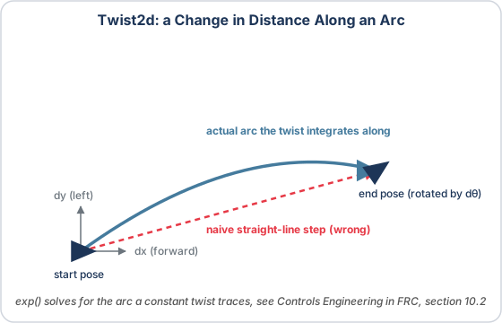
Calling .exp() on a Twist2d solves for that arc and returns the resulting Transform2d, the pose
delta the twist works out to once integrated. The underlying derivation, known as the pose exponential, is
covered in section 10.2 of Tyler Veness's Controls Engineering in the FIRST Robotics
Competition, which the Twist2d source itself
points to. The full mechanics of how this fits into a drivetrain's per-loop pose update, and why it matters for a
moving robot specifically, are covered in
Odometry.
Every type above has a 3D counterpart too: Translation3d, Rotation3d (backed by a quaternion instead of a
single angle), Pose3d, Transform3d, and Twist3d. 190's code stays in 2D almost everywhere, since the
robot itself only ever moves across a flat field, but drops into 3D wherever the underlying math genuinely is
three-dimensional: a camera's solve for an AprilTag's position (see Pose
Estimation) and AdvantageScope's 3D mechanism
visualizations both work in Pose3d/Transform3d.
Uses in Robot Code
Mirroring poses across the field. Because the field frame never moves,
code written from the blue alliance's perspective has to explicitly flip itself for red. AllianceFlipUtil (inspired by FRC 6328) does
exactly that by composing a Translation2d with a coordinate flip and a Rotation2d with a 180 degree
rotation:
Show code
public static Translation2d apply(Translation2d translation) {
  return new Translation2d(applyX(translation.getX()), applyY(translation.getY()));
}

public static Rotation2d apply(Rotation2d rotation) {
  return shouldFlip() ? rotation.rotateBy(Rotation2d.kPi) : rotation;
}

public static Pose2d apply(Pose2d pose) {
  return new Pose2d(apply(pose.getTranslation()), apply(pose.getRotation()));
}
Driving to a target pose. AutoAlignCommand takes a target Pose2d directly as one of its constructor
arguments, then runs one ProfiledPIDController per axis (x, y, heading) against the error between
that target and the robot's current pose, combining the three outputs into a single ChassisSpeeds every cycle.
The target never needs to be converted into anything else first, a Pose2d is already exactly the right shape to
describe "drive here, facing this way."
Safety checks before trusting a pose. A bad vision measurement or an uninitialized sensor can produce a
Pose2d full of NaNs or sitting exactly at the origin, either of which would corrupt anything it gets
composed into. GeometryUtil.isNaN(Pose2d) and GeometryUtil.isZero(Pose2d) exist specifically to catch
that before a pose is trusted anywhere else in the codebase.
Odometry and vision. Every drivetrain integrates a Twist2d once per loop to update its best-guess pose,
covered fully in Odometry, and every vision pose estimate is really a chain of
Transform3ds (robot to camera, camera to tag, tag to field) composed together, covered fully in Pose
Estimation. Both are, underneath everything else on this page, just the
plus()/minus() composition rules above applied to real sensor data.